Editor’s note. Guest blogger, Alejandro Rivera, Aerospace Engineer at Goddard Space Flight Center,* argues that using math software to ensure accuracy should be part of any engineer’s FEA / CAE Process.
Leading competing programs during the space race were two giants of aerospace engineering: on the American side, rocket engineer Dr. Wernher von Braun, and on the Soviet side, astronautics genius Sergei Korolev.
While both represented entirely opposite systems and ideologies, they had one thing in common: both used identical German Albert Nestler A.G. slide rules for their calculations regarding plans and rockets to put a man on the moon. Their slide rules, which today can be found at the National Air and Space Museum in Washington DC, were considered at the time the most accurate and precise.
The slide rule used by engineers on the Mercury, Gemini, and Apollo programs is arguably the computing device that put a man on the moon. That and paper and pencil were NASA engineers’ main tools. Back then, there was no Finite Element Analysis software – as it only became available to a few engineers in the late 1960s and saw a very limited use – and certainly no powerful desktop and laptop computers like we have today.
It was Thomas G. Butler from NASA Goddard Space Flight Center who championed the creation of a general-purpose finite element analysis (FEA) software.
A contract was awarded to CSC, the Martin Company, and MacNeal-Schwendler Corporation (MSC) who developed NASTRAN (NAsa STRuctural ANalysis) and delivered it to NASA in 1968. In 1972 Hewlett-Packard introduced the first handheld electronic calculator. It was so successful that almost instantly the slide rule became obsolete.
Finite element analysis began to see more widespread use in NASA throughout the 70s during the design of the Space Shuttle.
Fifty years later, today’s engineers have high-performance computing and engineering analysis tools on our personal computers that help us perform finite element analysis, dynamics, orbital mechanics analysis, etc. Their goal is to facilitate and speed up the analysis and overall engineering process.
Today’s typical FEA process can be summarized in the figure shown below. Given, for example, a stress analysis related problem, the software’s pre-processor is used to create the model. Typically, this involves importing the geometry, creating the mesh, and specifying boundary conditions, loads, materials, etc. The pre-processor then assembles the data into a format that is suitable for execution by the solver. The solver or processor runs all the computations, generating and then solving the system of equations. The post processor accepts the numeric solution and produces graphic displays of the data that allow the user to interpret the results. Several iterations are usually required to achieve a properly converged solution.
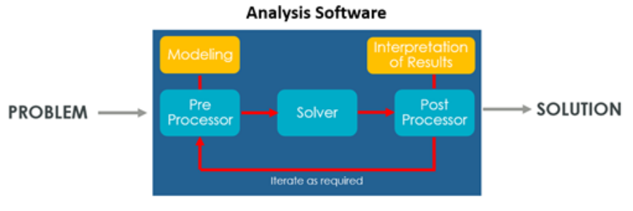
Fig. 1: Standard process for solving an analysis problem
As part of the FEA / CAE process, I personally try to involve Mathcad Prime as much as possible. As an example, given a dynamics analysis problem this is the approach I will follow:
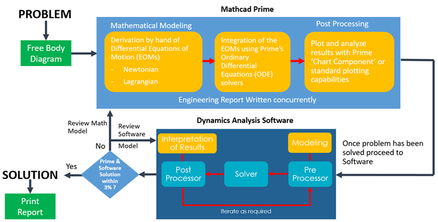
Fig 2: Author’s process for solving a dynamics problem using Mathcad Prime and analysis software
By using Mathcad Prime to develop the mathematical model and integrate the differential equations of motion, I can better understand what is occurring, becoming more with engaged with the process.
I feel that this also enhances my analytical skills and allows me to gain a better understanding of the physics involved. By the time the problem reaches the professional software package, I have minimized the potential for modeling errors and can compare the software result to that obtained from Mathcad. That in turn reduces the risk that I could blindly accept faulty software results. Using Mathcad to check fundamental principles such as conservation of momentum and energy is also easy and convenient.
A bonus to this approach? No more headaches creating reports as the worksheet builds them from the beginning. You no longer must merge information from Excel and the analysis software into the word processor or deal with the painful equation editor.
Changes and updates to the analysis are automatically captured via Mathcad Prime’s all-encompassing platform. Being able to share the analysis findings without imposing a skillset on the reader such as MATLAB®, FORTRAN®, etc. is an extra plus.
Overall, when using this approach, the engineer regains control of the analysis and the overall process can even become more gratifying. Personally, I enjoy solving a problem by hand and seeing how all the dynamics involved come into play much more than just pressing a button and letting the software assemble the system of differential equations and solve them for me.
A common argument against solving problems by hand is that “the geometry of my problem or the number of components in my engineering system is way too complex, so I can only do it with the software.”
I argue that the ability to synthesize a complex problem into its key elements to a level that can be solved by hand and obtain a close solution is an “art” that is less and less common nowadays yet one that should be practiced as frequently as possible.
Developing these skills can prove extremely helpful for any engineer. So next time you are ready to press the button to run your analysis model, ask yourself: “Do I fully understand all the engineering principles and mechanics involved in this problem?”
If the answer is no, a simple Mathcad Prime mathematical model could be all you need to feel more comfortable about your modeling approach and solution. Chances are you will enjoy the process more, and along the way, you will become a better engineer.
* The views, methods and opinions expressed in this article are those of the author and do not necessarily reflect the official policy, procedures or position of NASA Goddard Space Flight Center or the National Aeronautics and Space Administration. NASA does not promote or endorse any products and this article does not represent an endorsement of Mathcad Prime.
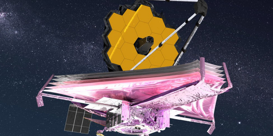
James Webb space telescope image courtesy NASA
The author is not affiliated to PTC in any form and received no financial compensation for this article.
Monthly tips, events, news, and inspiration