Editor's note: This blog article was originally written as a PTC Mathcad Prime worksheet. For the best reading experience, please download the Mathcad Prime 8 worksheet here. If you need a Mathcad Prime worksheet viewer, download Mathcad Prime for free here.
In previous blogs, we learned how to create shear and bending moment diagrams using free body diagrams. I also explained how Mathcad can be used to calculate the maximum bending moment for three loading conditions.
In this blog, I will derive functions for the shear, moment, slope, and deflection for a uniformly loaded, simply supported beam starting only with the loading condition and using integration. The process will then be repeated for a triangular loading.
When integrating, Mathcad does not include the integration constant C. This will need to be solved using known constraints.
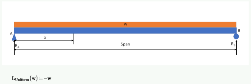
Since the uniform load is acting downward, I will use a negative value for w (force/length).
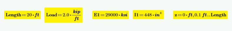
I will also use some numeric data to verify the calculated functions:
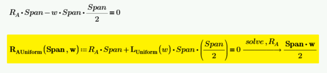
Calculate the left reaction by summing moments about point B.
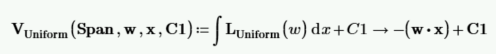
Calculate the shear function by integrating the load function and including the integration constant C1.
Solve for the integration constant C1. We know that at x=0, the shear is equal to the left reaction, RA.
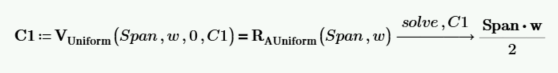
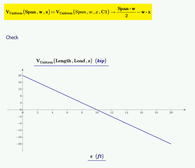
C1 is equal to Span*w/2. It can now be input into the function for shear, and the function for shear can be redefined without the need for C1 as an input variable.
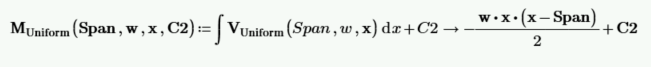
Calculate the moment function by integrating the shear function and including the integration constant C2.
Solve for the integration constant C2. We know that at x=0, the moment is 0.
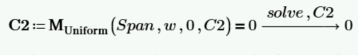
C2 is equal to 0. It can now be input into the function for moment, and the function for moment can be redefined without the need for C2 as an input variable.
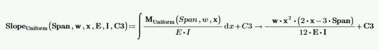
The relationship for the radius of curvature p, of a beam is defined from mechanics of materials as 1/p = M/(E*I), and the relationship of moment to slope, θ, is defined as M = E * I * d/dx(θ). Calculate the slope by integrating M/(E*I).
There are two ways to solve for C3 for a uniformly loaded beam.
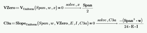
First, we know that for a uniformly loaded beam, the beam slope is equal to zero at the point of maximum moment, and we know that the maximum moment occurs at the location where the shear is equal to zero. The first way to solve for C3 is to calculate the location of zero shear, and use the constraint of slope=0 at the location of zero shear.
The second way to calculate C3 is to wait until the function for deflection is derived and use the two locations where the deflection is equal to zero. Then use two equations to solve for the two unknowns C3 and C4.
Calculate the deflection by integrating the slope function. Note that there are two constants of integration that must be solved.

C3 and C4 are unknown. The deflection at x=0 is 0, and the deflection at x=Span is 0. Use these two values to solve for C3 and C4.
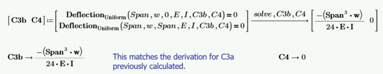
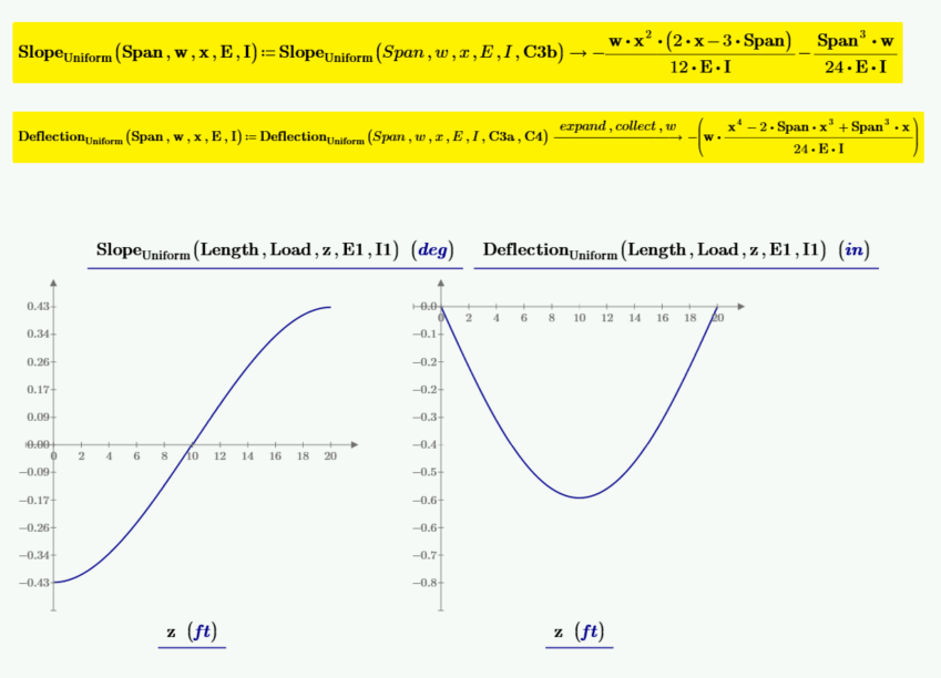
C3 is equal to -((span3 * w) / (24 * E * I)). It can now be input into the function for slope, and the function for slope can be redefined without the need for C3 as an input variable. C4 is equal to zero, and C4 can be eliminated.
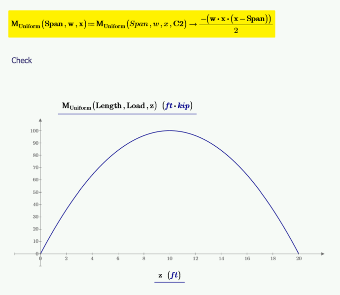
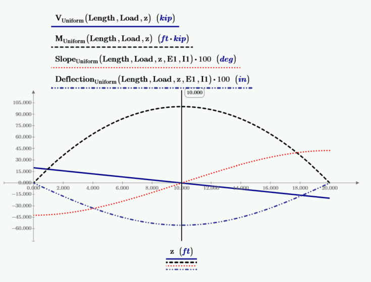
The below plot has plots of shear, moment, beam slope, and deflection. The values of slope and deflection are multiplied by 100 to allow them to plot at the needed scale. The vertical marker, located at mid-span, is at the location of zero shear, maximum moment, zero slope, and maximum deflection.
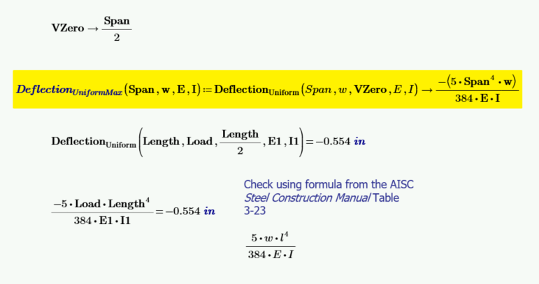
Derive a function to calculate the maximum deflection for a uniformly loaded beam. The maximum deflection occurs where the beam slope is 0, where the moment is greatest, and where the shear is 0. This value, VZero, was calculated earlier.
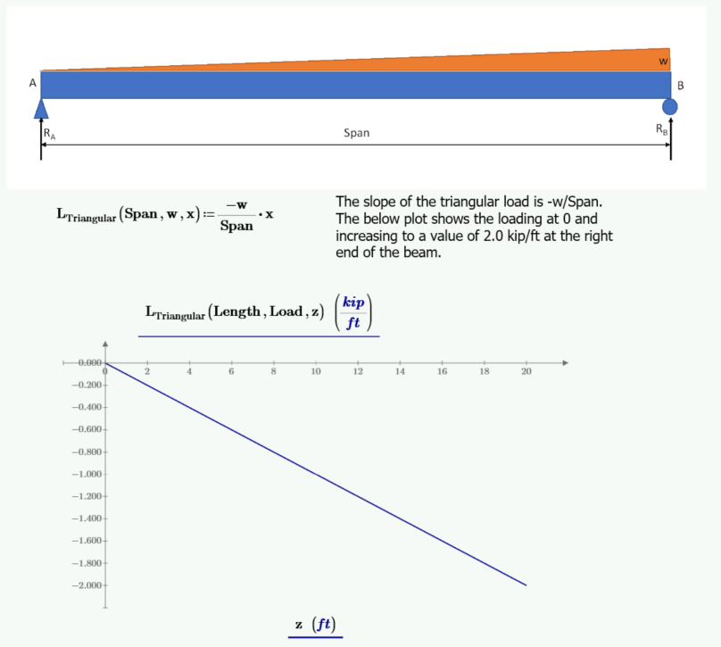
The following example repeats the process used above to derive functions to calculate the shear, moment, slope, and deflection for a triangular loaded beam, beginning with a triangular load function.
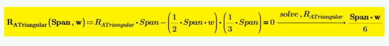
Calculate the left reaction by summing moments about point B.
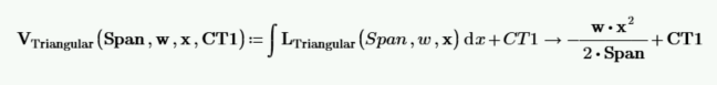
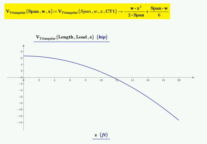
Calculate the shear function by integrating the load function and including the integration constant CT1.
Solve for the integration constant CT1. We know that at x=0, the shear is equal to the left reaction, RA.
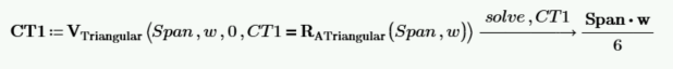
CT1 is equal to Span*w/6. It can now be input into the function for shear, and the function for shear can be redefined without the need for CT1 as an input variable.
Calculate the moment function by integrating the shear function and including the integration constant CT2.

Solve for the integration constant CT2. The moment at x=0 is 0.
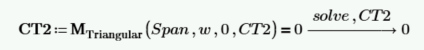
CT2 is equal to 0. It can now be input into the function for moment, and the function for moment can be redefined without the need for CT2 as an input variable.
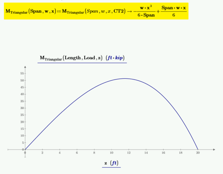
The relationship for the radius of curvature, p, of a beam is defined from mechanics of materials as 1/p = M/E * I, and the relationship of moment to slope, θ, is defined as M = E * I * d/dx(θ). Calculate the slope by integrating M/E * I.
For the case of triangular loading, the maximum deflection does not occur at the location of zero shear and maximum moment. Because of this, we do not know of any constraints to solve for CT3.
For this case, the only way to solve for CT3 is to wait until the function for deflection is derived and then use the two locations where the deflection is equal to zero to solve for the two unknowns CT3 and CT4.
Calculate the deflection by integrating the slope function. Note that there are two constants of integration that must be solved.

CT3 and CT4 are unknown. The deflection at x=0 is 0, and the deflection at x=Span is 0. Use these two values to solve for CT3 and CT4.
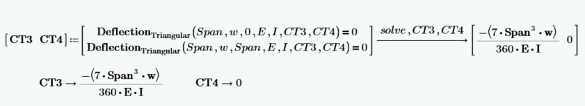
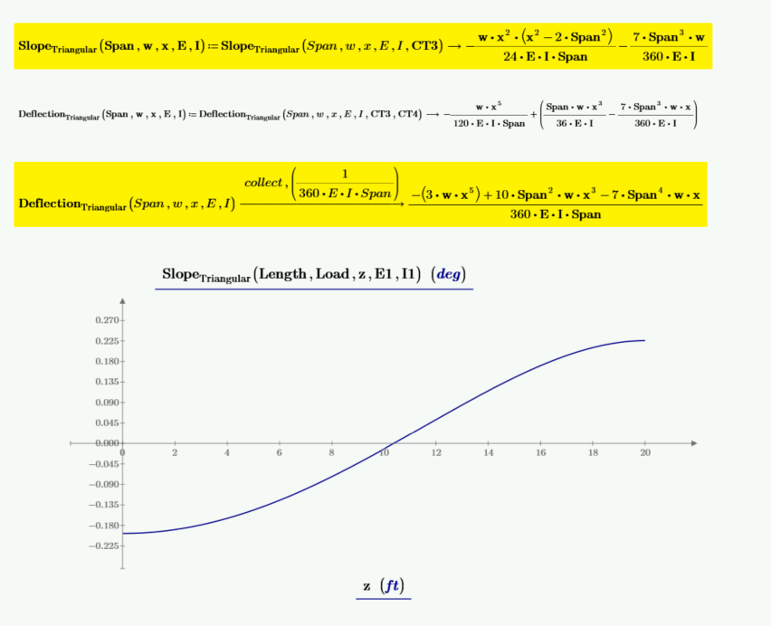
Now that CT3 and CT4 are known, the function for slope and deflection can be redefined.
Derive a function to calculate the maximum deflection for a triangular load, which occurs where beam slope equals zero. The solution for x has four solutions.
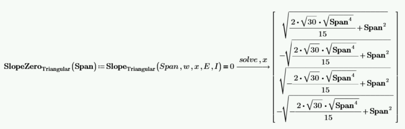
Check the numeric results and select the 3rd solution for the location of zero beam slope. Note: The subscript 3 is obtained using the left bracket [.
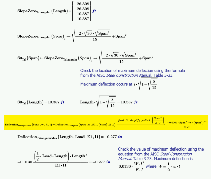
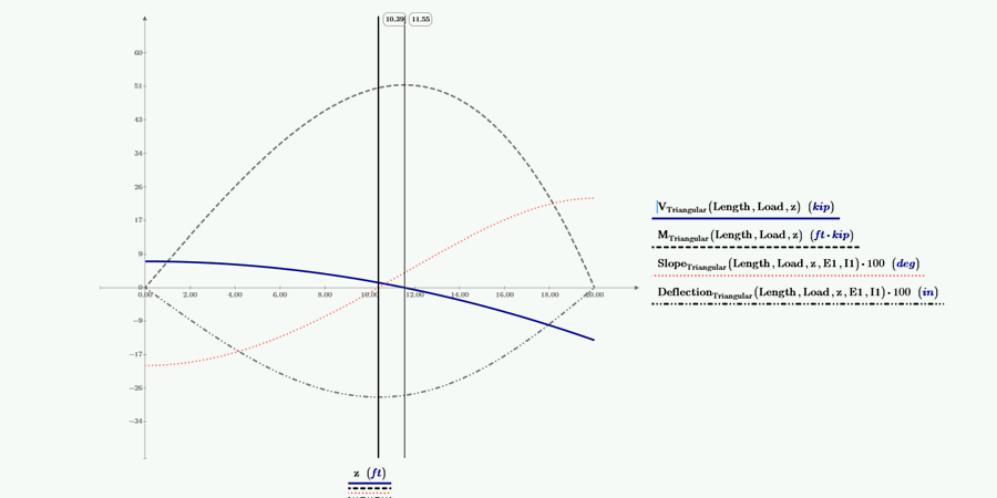
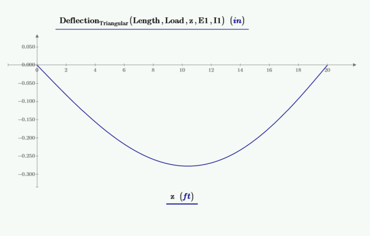
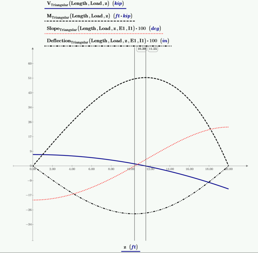
The below plot has plots of shear, moment, beam slope, and deflection. The values of slope and deflection are multiplied by 100 to allow them to plot at the needed scale. The left vertical marker is at the location of zero beam slope and at the location of the maximum deflection. The right vertical marker is at the location of zero shear and maximum moment.
In this blog, I have used integration to derive functions for deflection starting only with a loading function. Along the way, I derived functions for shear, bending moment, and beam slope. These functions were checked using known equations from the AISC Steel Construction Manual.
Integration is a powerful tool in the Mathcad tool box. I demonstrated how to solve for the constants of integration by using known constraints and how to use the solve keyword with the Symbolic Evaluation Operator along with other keywords to help derive the desired functions.
In this blog, I used loading on beams to illustrate the concepts, but these same concepts can be used in numerous other fields of science and engineering. The examples in this blog illustrate the use of:
Download a free 30-day trial of Mathcad Prime to see the best of Mathcad for yourself.